Category Archives: Industry

Industry

how to get insurance coverage to include blown motor

When it arrives to getting insurance policy protection for a blown motor, it is dependent on the certain phrases and ailments of your insurance coverage policy. Commonly, normal vehicle coverage insurance policies do not go over mechanical failures or normal put on and tear. Even so, there are a number of methods you can consider:

one. Evaluation your coverage coverage: Carefully read by way of your insurance plan files to understand what is lined and what is excluded. Glance for any clauses or provisions related to mechanical failures or engine destruction.

2. Call your insurance plan organization: Achieve out to your insurance policy supplier and inform them about the blown motor. Demonstrate the problem and question if there is any coverage offered underneath your coverage. Be well prepared to deliver particulars about the induce of the blown motor and any applicable documentation or China motor supplier proof.

three. Take into consideration more protection: If your conventional insurance policy plan does not go over mechanical failures, you may perhaps have the possibility to invest in additional coverage, this kind of as mechanical breakdown insurance (MBI) or an extended warranty. These kinds of coverage especially guard versus unexpected mechanical failures.

4. Discover other avenues: If your coverage coverage does not deliver protection for China motor supplier a blown China motor supplier and you do not have supplemental protection, you might need to think about other selections. This could incorporate paying out for the repairs out of pocket, searching for guidance from an extended warranty service provider if applicable, or discovering any possible recourse against the manufacturer or dealership if the blown motor resulted from a defect or carelessness.

It really is important to be aware that each coverage policy and predicament is unique, so it's most effective to check with with your insurance coverage provider immediately to have an understanding of your precise coverage and choices regarding a blown motor.

how to design plastic injection molded components

Designing plastic injection molded elements includes several issues to be certain productive and productive producing. Below are some methods to manual you via the system:

one. Outline Prerequisites: Clearly set up the purposeful and general performance specifications for the component. Consider elements this sort of as part geometry, product assortment, mechanical houses, dimensional tolerances, surface area finish, and any distinct industry requirements or laws.

2. Material Choice: Decide on a suited thermoplastic substance for injection molding centered on your prerequisites. Contemplate elements these types of as mechanical houses, chemical resistance, temperature resistance, price tag, and availability. Seek the advice of material datasheets and collaborate with product suppliers to make an informed conclusion.

three. Portion Geometry: Design the portion geometry with consideration for moldability, functionality, and aesthetics. Keep uniform wall thickness where ever possible to make certain proper movement of molten plastic through China Injection molded parts supplier molding. Incorporate attributes this kind of as draft angles, ribs, bosses, and fillets as essential.

4. Draft Angles: Incorporate draft angles (tapered surfaces) into the portion style and design to facilitate simple component ejection from the mould and keep away from undercuts. Ample draft angles usually array from .5 to 2 degrees, depending on the product and element measurement.

5. Wall Thickness: Manage reliable and suitable wall thickness all over the portion structure. Different wall thickness can guide to uneven cooling, warping, or sink marks. Intention for a wall thickness between one-5 mm, based on the element dimension and material.

6. Gate Placement: Identify acceptable gate spots for the injection of molten plastic into the mold cavity. Gate placement impacts the filling pattern, part visual appearance, and substance movement. Widespread gate forms consist of edge gates, pin-issue gates, or sub-gates. Avoid inserting gates on crucial surfaces or spots necessitating a large beauty finish.

seven. Ribs and Fillets: Incorporate ribs to raise section stiffness though reducing content utilization. Use fillets or rounded corners to reduce worry focus and facilitate materials move through molding. Maintain acceptable thickness and top ratios involving ribs and adjacent partitions to keep away from sink marks or warpage.

8. Parting Line: Set up the parting line, which is the separation line in between mould halves, and assure it does not interfere with essential surfaces or attributes. Style the parting line to allow for correct mould opening and portion ejection.

9. Undercuts and Aspect Steps: Lessen or eliminate undercuts and aspect steps in the element design, as they complicate mould layout and improve producing fees. If undercuts or side steps are vital, system for supplemental mould characteristics like slides or lifters to accommodate them.

ten. Floor Complete and Texture: Specify the preferred area end and texture for the portion. Take into consideration beauty necessities, useful requirements (these kinds of as grip or slip resistance), and the abilities of the picked out mildew and substance.

eleven. Style for Manufacturing and Assembly: Take into consideration relieve of manufacturing and assembly for the duration of the layout course of action. Reduce the amount of factors, use snap-suit or interlocking characteristics wherever ideal, and be certain correct alignment and match involving mating parts.

12. Prototyping and Screening: Develop prototypes or 3D-printed styles to assess the design, fit, operation, and functionality of the injection molded aspect. Conduct tests to validate the design against the defined prerequisites.

Collaborating with knowledgeable mildew designers and companies is extremely proposed in the course of the structure method to optimize the element structure for prosperous injection molding. They can provide useful insights, provide layout responses, and aid tackle probable manufacturing problems. Also, making use of mould circulation simulation application can help discover and solve potential problems right before going ahead with output.

Link

CV joint failure is not uncommon, specially in vehicles with greater mileage or those subjected to severe driving ailments. Even though cv joint factory joints are created to be resilient, they are nevertheless topic to put on and tear about time. The frequency of CV joint failure can rely on quite a few factors, together with:

1. Driving circumstances: Regular velocity joints can be extra susceptible to failure in cars that are regularly pushed on rough or uneven terrain, as perfectly as all those uncovered to excessive grime, gravel, or road particles. Intense off-road driving, intense acceleration, and repeated sharp turns can also accelerate the use on CV joints.

2. Routine maintenance and care: Right maintenance and regime inspections of CV joints can assist recognize early symptoms of don or destruction. Often examining and changing weakened CV joint boots, protecting sufficient concentrations of grease, and addressing any irregular noises or vibrations immediately can help prolong the daily life of the CV joints.

3. Top quality of factors: The top quality of the CV joints and associated components can effect their longevity. Making use of substantial-top quality, OEM (Initial Gear Company) or highly regarded aftermarket CV joints can deliver better toughness and China cv joint effectiveness in contrast to decreased-quality or substandard elements.

4. Driving habits: Intense driving routines, this sort of as speedy acceleration, tough braking, or recurrent sharp turns, can put additional strain on the CV joints and increase the probability of failure.

When CV joint failure is not unusual, it is critical to observe that regular inspections, routine maintenance, and prompt repairs can enable mitigate the risk and increase the lifespan of the CV joints. If you knowledge any indications of a failing CV joint, it is suggested to have your automobile inspected by a skilled mechanic to handle the challenge promptly and prevent additional hurt.

Do cars have helical gears?

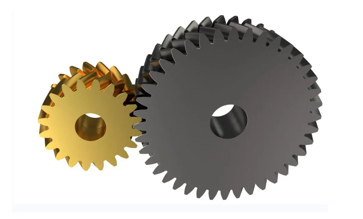
helical gears are normally applied in automotive apps, including in autos. China helical reducer supplier gears can be found in a variety of sections of a car's drivetrain and transmission technique. Listed here are a handful of examples:

one. Guide Transmissions: Many guide transmissions in autos utilize helical gears. These gears aid transmit electricity from the motor to the wheels, enabling the driver to change gears and command China helical reducer supplier the vehicle's pace and China helical reducer exporter torque. Helical gears in handbook transmissions present smoother and quieter gear shifting compared to straight-slice (spur) gears.

2. Differential Gears: The differential is a critical component in a car's drivetrain that allows the wheels to rotate at distinct speeds while cornering. Helical gears are typically utilised in the differential to transmit energy from the driveshaft to the wheels. The angled enamel of helical gears assistance distribute torque evenly and cut down noise and vibration during procedure.

3. Equipment Reduction Units: In some cases, helical gears are employed in equipment reduction devices in the drivetrain. These devices are utilized to alter the rotational speed and torque among various factors, these kinds of as the engine and the wheels. Helical gears in gear reduction techniques give effective power transmission and load distribution.

4. Timing Gears: Helical gears may perhaps also be used in a car's timing program, particularly in overhead camshaft (OHC) engines. Timing gears synchronize the opening and closing of the engine's valves with the rotation of the crankshaft. Helical gears in timing techniques assure precise and smooth procedure, contributing to the engine's effectiveness and efficiency.

It can be truly worth noting that when helical gears are generally utilised in automobiles, other equipment types, these as spur gears, bevel gears, and worm gears, may perhaps also be used in distinct automotive programs dependent on their particular benefits and needs.

what is the parting line in injection molding

In China Injection molded parts manufacturer molding, the parting line refers to the separation line or boundary amongst the two halves of the mold, identified as the cavity and the core. The parting line determines how the mildew opens and closes to develop the wished-for condition of the injection molded component.

When the mildew is closed, molten plastic is injected into the cavity, filling the space and getting the shape of the mold. The parting line is exactly where the two mildew halves fulfill and make a slight seam or line on the surface area of the finished portion.

The parting line can be positioned in diverse positions relying on the layout of the portion and the mildew. It is normally positioned at a area that minimizes its visibility and impression on the part's visual appearance and functionality. Nevertheless, in some instances, the parting line may be intentionally positioned in a specific site for functional or aesthetic reasons.

The style and design of the aspect and the mildew ought to think about the parting line to assure proper mildew opening and closing, as effectively as productive ejection of the molded part. It is important to assure that the parting line does not intersect crucial surfaces, features with restricted tolerances, or China Injection molded parts manufacturer regions demanding a high beauty finish.

For the duration of the injection molding system, the parting line can go away a modest seam or flash on the finished portion. Flash is an excessive layer of product that can arise at the parting line due to the slight hole among the mold halves. Proper mold design and routine maintenance enable decrease flash to accomplish the wanted section high quality.

General, the parting line performs a essential role in the injection molding approach as it defines how the mold is break up and determines the look and performance of the closing injection molded component.

how to connect rhode equipment bicycle rack?

Attaching a Rhode China gear rack distributor bike rack usually involves securing it to the rear of your auto. Here is a common information on how to attach a Rhode Gear bike rack:

Be aware: The specific recommendations may well differ relying on the product of your Rhode Gear bicycle rack. It is really important to consult with the rack's instruction guide for thorough recommendations and any certain specifications.

Resources Needed:

- Rhode Equipment bike rack

- Adjustable wrench or Allen wrench (if necessary)

- Rubber straps or bungee cords (if provided)

Recommendations:

1. Preparation:

- Make sure that your car or truck is parked on a degree surface area and the parking brake is engaged.

- If you have a hitch-mounted bicycle rack, ensure that your automobile has a hitch receiver put in. The hitch receiver must match the sizing and class specified by the bike rack's instructions.

2. Place the bike rack:

- Placement the bicycle rack near the rear of your automobile, aligning it with the hitch receiver or trunk space. Make sure that the rack is centered and degree.

3. Hitch-mounted bike rack:

- If you have a hitch-mounted bike rack, slide the shank of the rack into the hitch receiver. Align the holes on the shank with the hitch pin holes.

- Insert the hitch pin or bolt via the holes and protected it tightly. Some racks may possibly call for the use of a wrench or Allen wrench to tighten a bolt.

- Use any locking mechanisms or anti-rattle devices delivered with the rack to secure it even further and lower movement whilst driving.

4. Trunk-mounted bicycle rack:

- If you have a trunk-mounted bike rack, placement the rack on the trunk or rear hatch of your car or truck in accordance to the manufacturer's guidelines.

- Assure that the rack is secure and steady on the trunk or hatch. Some trunk-mounted racks use straps or hooks that attach to the edges of the trunk or hatch.

- Attach the straps or hooks to the correct destinations, guaranteeing a restricted and safe in shape. Comply with the manufacturer's directions on how to appropriately safe the rack to your unique vehicle.

five. Protected the bikes:

- After the bicycle rack is securely connected, meticulously put your bikes on to the rack.

- Connect the bicycle frames to the selected mounting details on the rack. Most racks have adjustable straps or clamps that protected the bicycle frames in place.

- Make sure the bikes are evenly dispersed and appropriately secured to reduce any movement or injury for the duration of transportation.

6. Confirm stability:

- Soon after loading the bikes, carefully shake the rack and bikes to be certain they are steady and properly secured. Check out that there is no too much movement or wobbling.

- If necessary, use more rubber straps or bungee cords (if provided with the rack) to further more protected the bikes and reduce them from shifting through transit.

Usually make certain that the bike rack and bikes do not hinder your rear lights, license plate, or visibility although driving. Furthermore, it truly is significant to follow any added instructions or recommendations provided by Rhode Equipment for your particular product of bicycle rack.

What is coupling and case in point?

In a standard sense, a coupling is a machine or mechanism utilized to link two separate objects or components together. Couplings are typically employed in various fields, this kind of as mechanics, engineering, and electrical methods, to sign up for or url distinctive pieces.

Below are a several illustrations of couplings:

1. Mechanical Couplings: Mechanical couplings are made use of to link two rotating shafts in equipment and products. Some widespread examples include:

a. Sleeve or Muff Coupling: This kind of coupling is made up of a hollow cylindrical sleeve that suits in excess of the ends of two shafts, with keys or splines giving a secure connection.

b. Clamp or Break up Coupling: Clamp couplings have two halves that are tightened all over the shaft ends applying bolts or clamps, creating a rigid link.

c. Equipment Coupling: Equipment couplings use interlocking tooth on the China coupling halves to transmit torque when permitting for a sure volume of misalignment.

two. Electrical Couplings: Electrical couplings are used to link and transmit electrical alerts concerning distinctive components or programs. Examples include:

a. Wire Connectors: Wire connectors, this kind of as twist-on wire nuts or crimp connectors, are used to be a part of electrical wires securely.

b. Plug and Socket Connectors: These couplings consist of male and female connectors that enable the relationship and disconnection of electrical products, these as electrical power cords or audio cables.

c. Terminal Blocks: Terminal blocks deliver a hassle-free way to join many wires or electrical conductors in a command panel or junction box.

3. Fluid Couplings: Fluid couplings use hydraulic concepts to transmit electrical power in between two components. Examples contain:

a. Hydraulic Couplings: Hydraulic couplings, this kind of as swift-disconnect couplings, make it possible for for effortless and safe relationship and disconnection of hydraulic traces.

b. Pneumatic Couplings: Pneumatic couplings are used to connect and disconnect air source lines in pneumatic devices, these as in air compressors or pneumatic tools.

four. Optical Couplings: Optical couplings are applied in optical programs to be a part of or align optical fibers or parts. Examples include:

a. Fiber Optic Couplers: Fiber optic couplers permit the link of optical fibers, letting indicators to be transmitted between them.

b. Lens Couplings: Lens couplings are utilised to align and hook up lenses in optical units, guaranteeing proper concentrate and light-weight transmission.

These examples illustrate the varied assortment of couplings and their programs throughout various fields. Couplings enjoy a vital role in connecting and integrating many factors, enabling the productive transmission of power, alerts, or fluids concerning them.

are bmw automatic gearboxes responsible?

BMW automated gearboxes have normally been regarded reliable, but like any elaborate mechanical system, they can practical experience troubles in excess of time. The dependability of BMW computerized gearboxes can range dependent on factors such as the model, technology, particular transmission form, servicing record, and driving disorders. It really is vital to notice that person experiences and views may fluctuate.

BMW has utilized several automated transmission systems above the several years, which include common torque converter automatic transmissions and more highly developed systems this sort of as the ZF 8-speed automated transmission. These transmissions have been well-regarded for their clean operation, quick and precise shifts, and total effectiveness.

To preserve the dependability of a BMW computerized gearbox, it really is critical to stick to the manufacturer's proposed routine maintenance agenda, which ordinarily incorporates typical fluid adjustments. Satisfactory transmission fluid stages and thoroughly clean fluid assist make certain suitable lubrication and cooling, lowering dress in on inside elements.

However, it is really value noting that no mechanical procedure is solely immune to probable difficulties. Some typical troubles that can arise with computerized gearboxes, which includes people in BMW automobiles, may well include:

1. Electronic and Sensor Problems: Contemporary computerized gearboxes depend on sophisticated electronic controls and sensors. Difficulties with electronic elements or sensors can direct to shifting problems or fault codes currently being brought on.

2. Fluid Leaks: Over time, seals or China gearbox gaskets in the gearbox could deteriorate, top to fluid leaks. Inadequate fluid amounts can induce improper procedure and potential hurt to the gearbox.

three. Mechanical Dress in: As with any transmission, dress in and tear can take place around time. This may include things like put on on clutches, bands, or equipment teeth, which could manifest as slipping, severe shifting, or abnormal noises.

4. Valve Physique Concerns: The valve entire body is a significant ingredient that controls the circulation and routing of transmission fluid. Issues with the valve physique, this kind of as sticking valves or solenoids, can have an effect on equipment shifts and overall transmission effectiveness.

Whilst these issues can come up, it's significant to be aware that a lot of BMW owners have had positive activities with the reliability of their computerized gearboxes. Frequent servicing, China gearbox distributor prompt addressing of any difficulties, and driving in the transmission's constraints can assistance manage the trustworthiness of a BMW automatic gearbox.

If you are considering a particular BMW design or have issues about a specific gearbox, it is a good idea to research the model's dependability heritage, consult with BMW authorities or owners' communities, and have a pre-purchase inspection executed by a competent mechanic to assure the China gearbox's problem satisfies your expectations.

What component is a cog?

A cog generally refers to a single tooth on a equipment. In the context of gears, China gear a cog is one particular of the person tooth that make up the equipment mechanism. Gears consist of numerous cogs or China gear tooth that mesh with each other to transmit energy and movement.

So, to be obvious, a cog is not a individual element or element unique from a equipment. As an alternative, it is a time period that precisely refers to an particular person tooth on a gear. Gears are designed up of numerous cogs, and these cogs work collectively to form the finish gear mechanism.

When discussing gears, it is widespread to refer to the collective arrangement of cogs or teeth on a equipment alternatively than concentrating on unique cogs. On the other hand, in certain contexts, the phrase "cog" could be employed to explain an specific tooth or the toothed portion of a China gear.

how to structure rack and pinion equipment?

Coming up with a rack and pinion gear process will involve numerous issues, together with the technical specs, proportions, and application needs. Here is a typical tutorial on how to layout a rack and pinion equipment:

one. Figure out the specs:

- Outline the software prerequisites and parameters, these as the preferred linear motion, load capacity, speed, and torque.

- Decide the preferred gear ratio, which signifies the relationship concerning the rotation of the pinion gear and the linear displacement of the rack.

2. Determine proportions:

- Establish the necessary duration of the rack. This will rely on the linear vacation distance essential for your software.

- Compute the quantity of tooth for the pinion gear. The variety of tooth will influence the equipment ratio and must be selected based mostly on the sought after motion and torque necessities.

3. Pick out equipment module or pitch:

- Gear module (for metric units) or gear pitch (for imperial programs) decides the size and spacing of the equipment teeth.

- Opt for a gear module or pitch acceptable for your application based on aspects these kinds of as load, velocity, and out there manufacturing selections.

four. Layout the equipment profiles:

- Decide the equipment profile form, these kinds of as involute or cycloidal, dependent on your unique requirements and manufacturing capabilities.

- Use gear structure application or reference tables to crank out the equipment tooth profile dependent on the selected equipment module or pitch.

five. Take into consideration backlash and clearance:

- Account for backlash, which refers to the modest hole amongst the enamel of the rack and pinion gears. Appropriate backlash is needed to avert binding and make sure smooth operation.

- Establish the demanded clearance involving the rack and pinion gear to accommodate production tolerances and thermal growth.

six. Look at for China gear rack supplier interference and tooth power:

- Validate that there is no interference involving the rack and pinion gear, making certain that the enamel mesh properly with no any collisions.

- Conduct power calculations to assure that the equipment tooth can endure the used loads devoid of failure. Take into consideration aspects these types of as materials properties, tooth width, and call pressure.

seven. Think about lubrication and servicing:

- Figure out the lubrication needs for the gear technique to decrease friction and dress in. Decide on an appropriate lubricant dependent on the running disorders and products used.

- Program for regular maintenance and inspection to ensure the equipment program remains in great functioning situation.

8. Prototype and tests:

- Make a prototype or 3D model of the China gear rack supplier method to validate the style and design and evaluate its effectiveness.

- Carry out screening to appraise aspects these types of as backlash, load ability, performance, and longevity. Make any necessary adjustments or iterations dependent on the examination results.

Take note: Coming up with rack and pinion gears needs experience in equipment style and production. It is proposed to check with with a mechanical engineer or a gear style specialist, employ specialized equipment style and design program, and refer to applicable expectations and suggestions for a thorough and exact layout.