Product Description
Product Description
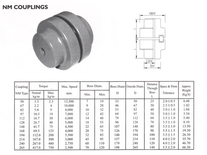
COUPLINGS
| HRC | FCL | Chain coupling | GE | L | NM | MH | Torque limiter |
| HRC 70B | FCL90 | KC4012 | GE14 | L050 | NM50 | MH45 | TL250-2 |
| HRC 70F | FCL100 | KC4014 | GE19 | L070 | NM67 | MH55 | TL250-1 |
| HRC 70H | FCL112 | KC4016 | GE24 | L075 | NM82 | MH65 | TL350-2 |
| HRC 90B | FCL125 | KC5014 | GE28 | L090 | NM97 | MH80 | TL350-1 |
| HRC 90F | FCL140 | KC5016 | GE38 | L095 | NM112 | MH90 | TL500-2 |
| HRC 90H | FCL160 | KC6018 | GE42 | L099 | NM128 | MH115 | TL500-1 |
| HRC 110B | FCL180 | KC6571 | GE48 | L100 | NM148 | MH130 | TL700-2 |
| HRC 110F | FCL200 | KC6571 | GE55 | L110 | NM168 | MH145 | TL700-1 |
| HRC 110H | FCL224 | KC8018 | GE65 | L150 | NM194 | MH175 | |
| HRC 130B | FCL250 | KC8571 | GE75 | L190 | NM214 | MH200 | |
| HRC 130F | FCL280 | KC8571 | GE90 | L225 | |||
| HRC 130H | FCL315 | KC1571 | |||||
| HRC 150B | FCL355 | KC12018 | |||||
| HRC 150F | FCL400 | KC12571 | |||||
| HRC 150H | FCL450 | ||||||
| HRC 180B | FCL560 | ||||||
| HRC 180F | FCL630 | ||||||
| HRC 180H | |||||||
| HRC 230B | |||||||
| HRC 230F | |||||||
| HRC 230H | |||||||
| HRC 280B | |||||||
| HRC 280F | |||||||
| HRC 280H |
Catalogue
Workshop
Lots of coupling in stock
FAQ
Q1: Are you trading company or manufacturer ?
A: We are factory.
Q2: How long is your delivery time and shipment?
1.Sample Lead-times: 10-20 days.
2.Production Lead-times: 30-45 days after order confirmed.
Q3: What is your advantages?
1. The most competitive price and good quality.
2. Perfect technical engineers give you the best support.
3. OEM is available.
| Standard Or Nonstandard: | Standard |
|---|---|
| Structure: | Flexible |
| Material: | Steel |
| Type 7: | Nm148 |
| Type 6: | Nm128 |
| Type 9: | Nm194 |
| Customization: |
Available
| Customized Request |
|---|
Can flexible couplings be used in both horizontal and vertical shaft arrangements?
Yes, flexible couplings can be used in both horizontal and vertical shaft arrangements. The design of flexible couplings allows them to accommodate misalignment and compensate for angular, parallel, and axial displacements between the shafts, making them suitable for various shaft orientations.
Horizontal Shaft Arrangements:
In horizontal shaft arrangements, where the shafts are parallel to the ground or horizontal plane, flexible couplings are commonly used to connect two rotating shafts. These couplings help transmit torque from one shaft to another while accommodating any misalignment that may occur during operation. Horizontal shaft arrangements are common in applications such as pumps, compressors, conveyors, and industrial machinery.
Vertical Shaft Arrangements:
In vertical shaft arrangements, where the shafts are perpendicular to the ground or vertical plane, flexible couplings are also applicable. Vertical shafts often require couplings that can handle the additional weight and forces resulting from gravity. Flexible couplings designed for vertical applications can support the weight of the rotating equipment while allowing for some axial movement to accommodate thermal expansion or other displacements. Vertical shaft arrangements are commonly found in applications such as pumps, gearboxes, turbines, and some marine propulsion systems.
Considerations for Vertical Shaft Arrangements:
When using flexible couplings in vertical shaft arrangements, there are a few additional considerations to keep in mind:
- Thrust Load: Vertical shafts can generate thrust loads, especially in upward or downward direction. The flexible coupling should be selected based on its capacity to handle both radial and axial loads to accommodate these forces.
- Lubrication: Some vertical couplings may require additional lubrication to ensure smooth operation and reduce wear, particularly if they are exposed to high axial loads or extended vertical shafts.
- Support and Bearing: Proper support and bearing arrangements for the vertical shaft are essential to prevent excessive shaft deflection and ensure the flexible coupling functions correctly.
Overall, flexible couplings are versatile and adaptable to various shaft orientations, providing efficient power transmission and misalignment compensation. Whether in horizontal or vertical arrangements, using the appropriate flexible coupling design and considering the specific application requirements will help ensure reliable and efficient operation.
What are the factors to consider when choosing a flexible coupling for a specific system?
Choosing the right flexible coupling for a specific system requires careful consideration of several factors. The following are the key factors that should be taken into account:
- 1. Misalignment Requirements: Assess the type and magnitude of misalignment expected in the system. Different couplings are designed to handle specific types of misalignment, such as angular, parallel, or axial misalignment. Choose a coupling that can accommodate the expected misalignment to prevent premature wear and failure.
- 2. Torque Capacity: Determine the required torque capacity of the coupling to ensure it can transmit the necessary power between the shafts. Consider both the continuous and peak torque loads that the system may experience.
- 3. Operating Speed: Take into account the rotational speed of the system. High-speed applications may require couplings that can handle the additional centrifugal forces and balance requirements.
- 4. Temperature Range: Consider the operating temperature range of the system. Select a coupling material that can withstand the temperatures encountered without losing its mechanical properties.
- 5. Environment and Conditions: Evaluate the environmental conditions where the coupling will be used, such as exposure to moisture, chemicals, dust, or corrosive substances. Choose a coupling material that is compatible with the operating environment.
- 6. Space Constraints: Assess the available space for the coupling installation. Some couplings have compact designs suitable for applications with limited space.
- 7. Installation and Maintenance: Consider the ease of installation and maintenance. Some couplings may require special tools or disassembly for maintenance, while others offer quick and simple installation.
- 8. Torsional Stiffness: Evaluate the torsional stiffness of the coupling. A balance between flexibility and stiffness is essential to prevent excessive torsional vibrations while accommodating misalignment.
- 9. Shock and Vibration Damping: For applications with high shock loads or vibration, select a coupling with excellent damping characteristics to protect the system from excessive forces.
- 10. Cost and Budget: Compare the cost of the coupling with the overall budget for the system. Consider the long-term cost implications, including maintenance and replacement expenses.
Ultimately, the choice of a flexible coupling should align with the specific requirements and operating conditions of the system. Consulting with coupling manufacturers or engineering experts can provide valuable insights to ensure the optimal selection of a coupling that enhances system performance, reliability, and efficiency.
Can you explain the different types of flexible coupling designs available?
There are several types of flexible coupling designs available, each with its unique construction and characteristics. These designs are tailored to meet specific application requirements and address different types of misalignment and torque transmission needs. Here are some of the most common types of flexible couplings:
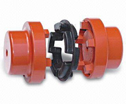
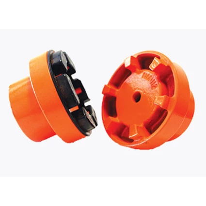
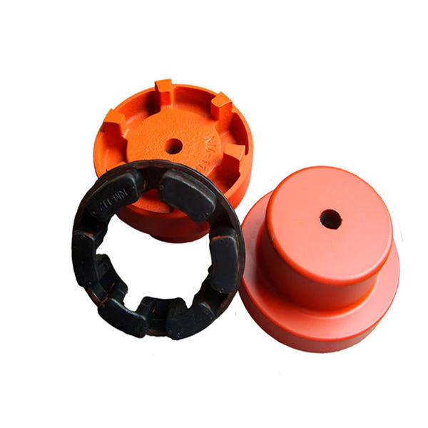
- Jaw Couplings: Jaw couplings consist of two hubs with curved jaws and an elastomer spider placed between them. The spider acts as a flexible element and can compensate for angular and parallel misalignment. Jaw couplings are widely used in various industrial applications due to their simple design and effectiveness in handling misalignment and vibration damping.
- Disc Couplings: Disc couplings use thin metallic discs with a series of alternating slits and flanges to connect the shafts. The disc coupling design allows for excellent misalignment compensation, including angular, parallel, and axial misalignment. Disc couplings are known for their high torsional stiffness and precise torque transmission capabilities.
- Gear Couplings: Gear couplings consist of toothed hubs connected by an external sleeve with gear teeth. They are well-suited for applications with high torque and moderate misalignment. Gear couplings offer good misalignment compensation and high torque capacity, making them popular in heavy-duty industrial applications.
- Beam Couplings: Beam couplings use a single piece of flexible material, often a metal beam, to connect the shafts. The material's flexibility allows for angular and axial misalignment compensation. Beam couplings are compact, lightweight, and provide low inertia, making them suitable for applications with high-speed requirements.
- Bellows Couplings: Bellows couplings consist of a bellows-like flexible structure that connects the two hubs. They can compensate for angular, parallel, and axial misalignment. Bellows couplings are known for their high torsional stiffness and ability to maintain constant velocity transmission.
- Oldham Couplings: Oldham couplings use three discs, with the middle one having a perpendicular slot. This design allows for angular misalignment compensation while transmitting torque between the hubs. Oldham couplings are often used when electrical isolation between shafts is required.
Each flexible coupling design has its strengths and limitations, and the choice depends on factors such as the application's torque requirements, misalignment conditions, operating environment, and speed. Proper selection of the coupling type ensures optimal performance, efficiency, and reliability in various mechanical systems and rotating machinery.


editor by CX 2023-08-10