Product Description
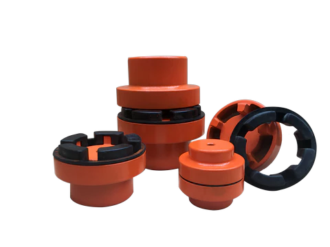
Stainless Steel Coupling Transmission Parts Gear High Quality Good Price Gear Roller Chain Couplings Nm Flange Flexible Elastomeric Stainless Steel Coupling
We are the leading top Chinese coupling manufacturer, and are specializing in various high quality coupling.
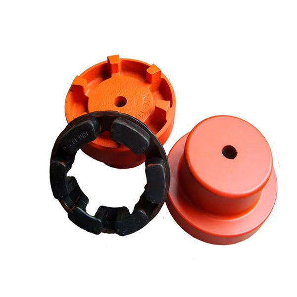
1. Material: Cast iron, Rubber.
2. OEM and ODM are available
3. High efficient in transmission
4. Finishing: Painted.
5. High quality with competitive price
6. Different models suitable for your different demands
7. Stock for different bore size on both sides available.
8. Application in wide range of environment.
9. Quick and easy mounting and disassembly.
10. Resistant to oil and electrical insulation.
11. Identical clockwise and anticlockwise rotational characteristics.
12. Small dimension, low weight, high transmitted torque.
13. It has good performance on compensating the misalignment.
Fluid couplings:
Features:
Improve the starting capability of electric motor, protect motor against overloading, damp shock, load
fluctuation and torsional vibration, and balance and load distribution in case of multimotor drives.
Applications:
Belt conveyers, csraper conveyers, and conveyers of all kinds Bucket elevators, ball mills, hoisters, crushers,
excavators, mixers, straighteners, cranes, etc.
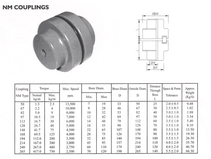
Flange Flexible Coupling:
Flexible Coupling Model is widely used for its compact designing,easy installation,convenientmaintenance,small size and
light weight.As long as the'relative displacement between shafts is kept within the specified tolerance,the coupling will
operate the best function and a longer working life,thus it is greatly demanded in medium and minorpower transmission
systems drive by moters,such as speed reducers,hoists,compressor,spining &weaving machines and ball mills,permittable
relative displacement:Radial displacement 0.2-0.6mm ; Angel displacemente 0o 30'--1o 30'
Jaw Couplings:
Click here for more types of couplings
Our Services:
1.Design Services
Our design team has experience in cardan shaft relating to product design and development. If you have any needs for your new product or wish to make further improvements, we are here to offer our support.
2.Product Services
raw materials → Cutting → Forging →Rough machining →Shot blasting →Heat treatment →Testing →Fashioning →Cleaning→ Assembly→Packing→Shipping
3.Samples Procedure
We could develop the sample according to your requirement and amend the sample constantly to meet your need.
4.Research & Development
We usually research the new needs of the market and develop the new model when there is new cars in the market.
5.Quality Control
Every step should be special test by Professional Staff according to the standard of ISO9001 and TS16949.
Company Information:
/* January 22, 2571 19:08:37 */!function(){function s(e,r){var a,o={};try{e&&e.split(",").forEach(function(e,t){e&&(a=e.match(/(.*?):(.*)$/))&&1
| Standard Or Nonstandard: | Standard |
|---|---|
| Shaft Hole: | 19-32 |
| Torque: | >80N.M |
| Bore Diameter: | 19mm |
| Speed: | 4000r/M |
| Structure: | Flexible |
| Samples: |
US$ 9999/Piece
1 Piece(Min.Order) | |
|---|
How does a flexible coupling handle angular, parallel, and axial misalignment?
A flexible coupling is designed to accommodate various types of misalignment between two rotating shafts: angular misalignment, parallel misalignment, and axial misalignment. The flexibility of the coupling allows it to maintain a connection between the shafts while compensating for these misalignment types. Here's how a flexible coupling handles each type of misalignment:
- Angular Misalignment: Angular misalignment occurs when the axes of the two shafts are not collinear and form an angle with each other. Flexible couplings can handle angular misalignment by incorporating an element that can flex and bend. One common design is the "spider" or "jaw" element, which consists of elastomeric materials. As the shafts are misaligned, the elastomeric element can deform slightly, allowing the coupling to accommodate the angular offset between the shafts while still transmitting torque.
- Parallel Misalignment: Parallel misalignment, also known as offset misalignment, occurs when the axes of the two shafts are parallel but not perfectly aligned with each other. Flexible couplings can handle parallel misalignment through the same elastomeric element. The flexible nature of the element enables it to shift and adjust to the offset between the shafts, ensuring continuous power transmission while minimizing additional stresses on the machinery.
- Axial Misalignment: Axial misalignment, also called end-play misalignment, occurs when the two shafts move closer together or farther apart along their common axis. Flexible couplings can handle axial misalignment through specific designs that allow limited axial movement. For instance, some couplings use slotted holes or a floating member that permits axial displacement while maintaining the connection between the shafts.
By providing the capability to handle angular, parallel, and axial misalignment, flexible couplings offer several advantages for power transmission systems:
- They help to prevent premature wear and damage to the connected equipment, reducing maintenance and replacement costs.
- They minimize vibration and shock loads, enhancing the overall smoothness and reliability of the machinery.
- They reduce the risk of equipment failure due to misalignment-induced stresses, improving the system's operational life.
- They allow for easier installation and alignment adjustments, saving time and effort during setup and maintenance.
Overall, flexible couplings play a crucial role in handling misalignment and ensuring efficient power transmission in various industrial applications.
What are the differences between elastomeric and metallic flexible coupling designs?
Elastomeric and metallic flexible couplings are two distinct designs used to transmit torque and accommodate misalignment in mechanical systems. Each type offers unique characteristics and advantages, making them suitable for different applications.
Elastomeric Flexible Couplings:
Elastomeric flexible couplings, also known as flexible or jaw couplings, employ an elastomeric material (rubber or similar) as the flexible element. The elastomer is typically molded between two hubs, and it acts as the connector between the driving and driven shafts. The key differences and characteristics of elastomeric couplings include:
- Misalignment Compensation: Elastomeric couplings are designed to handle moderate levels of angular, parallel, and axial misalignment. The elastomeric material flexes to accommodate the misalignment while transmitting torque between the shafts.
- Vibration Damping: The elastomeric material in these couplings offers excellent vibration dampening properties, reducing the transmission of vibrations from one shaft to another. This feature helps protect connected equipment from excessive vibrations and enhances system reliability.
- Shock Load Absorption: Elastomeric couplings can absorb and dampen shock loads, protecting the system from sudden impacts or overloads.
- Cost-Effective: Elastomeric couplings are generally more cost-effective compared to metallic couplings, making them a popular choice for various industrial applications.
- Simple Design and Installation: Elastomeric couplings often have a straightforward design, allowing for easy installation and maintenance.
- Lower Torque Capacity: These couplings have a lower torque capacity compared to metallic couplings, making them suitable for applications with moderate torque requirements.
- Common Applications: Elastomeric couplings are commonly used in pumps, compressors, fans, conveyors, and other applications that require moderate torque transmission and misalignment compensation.
Metallic Flexible Couplings:
Metallic flexible couplings use metal components (such as steel, stainless steel, or aluminum) to connect the driving and driven shafts. The metallic designs can vary significantly depending on the type of metallic coupling, but some general characteristics include:
- High Torque Capacity: Metallic couplings have higher torque transmission capabilities compared to elastomeric couplings. They are well-suited for applications requiring high torque handling.
- Misalignment Compensation: Depending on the design, some metallic couplings can accommodate minimal misalignment, but they are generally not as flexible as elastomeric couplings in this regard.
- Stiffer Construction: Metallic couplings are generally stiffer than elastomeric couplings, offering less vibration dampening but higher torsional stiffness.
- Compact Design: Metallic couplings can have a more compact design, making them suitable for applications with limited space.
- Higher Precision: Metallic couplings often offer higher precision and concentricity, resulting in better shaft alignment.
- Higher Cost: Metallic couplings are typically more expensive than elastomeric couplings due to their construction and higher torque capacity.
- Common Applications: Metallic couplings are commonly used in high-speed machinery, precision equipment, robotics, and applications with high torque requirements.
Summary:
In summary, the main differences between elastomeric and metallic flexible coupling designs lie in their flexibility, torque capacity, vibration dampening, cost, and applications. Elastomeric couplings are suitable for applications with moderate torque, misalignment compensation, and vibration dampening requirements. On the other hand, metallic couplings are chosen for applications with higher torque and precision requirements, where flexibility and vibration dampening are less critical.
Can you explain the different types of flexible coupling designs available?
There are several types of flexible coupling designs available, each with its unique construction and characteristics. These designs are tailored to meet specific application requirements and address different types of misalignment and torque transmission needs. Here are some of the most common types of flexible couplings:
- Jaw Couplings: Jaw couplings consist of two hubs with curved jaws and an elastomer spider placed between them. The spider acts as a flexible element and can compensate for angular and parallel misalignment. Jaw couplings are widely used in various industrial applications due to their simple design and effectiveness in handling misalignment and vibration damping.
- Disc Couplings: Disc couplings use thin metallic discs with a series of alternating slits and flanges to connect the shafts. The disc coupling design allows for excellent misalignment compensation, including angular, parallel, and axial misalignment. Disc couplings are known for their high torsional stiffness and precise torque transmission capabilities.
- Gear Couplings: Gear couplings consist of toothed hubs connected by an external sleeve with gear teeth. They are well-suited for applications with high torque and moderate misalignment. Gear couplings offer good misalignment compensation and high torque capacity, making them popular in heavy-duty industrial applications.
- Beam Couplings: Beam couplings use a single piece of flexible material, often a metal beam, to connect the shafts. The material's flexibility allows for angular and axial misalignment compensation. Beam couplings are compact, lightweight, and provide low inertia, making them suitable for applications with high-speed requirements.
- Bellows Couplings: Bellows couplings consist of a bellows-like flexible structure that connects the two hubs. They can compensate for angular, parallel, and axial misalignment. Bellows couplings are known for their high torsional stiffness and ability to maintain constant velocity transmission.
- Oldham Couplings: Oldham couplings use three discs, with the middle one having a perpendicular slot. This design allows for angular misalignment compensation while transmitting torque between the hubs. Oldham couplings are often used when electrical isolation between shafts is required.
Each flexible coupling design has its strengths and limitations, and the choice depends on factors such as the application's torque requirements, misalignment conditions, operating environment, and speed. Proper selection of the coupling type ensures optimal performance, efficiency, and reliability in various mechanical systems and rotating machinery.


editor by CX 2024-03-10
China wholesaler Rigid Coupling Transmission Parts Couplings Shaft Metal Stainless Steel Tooth Drum Curve Nm Chain Shaft Fexible Type of Rubber Best Manufacturers Rigid Coupling nm couplimg
Product Description
Rigid Coupling Transmission Parts Couplings Shaft Metal Stainless Steel Tooth Drum Curve NM Chain Shaft Fexible Type of Rubber Best Manufacturers Rigid Coupling
Application of Rigid Coupling
Rigid couplings are used to connect 2 shafts that are perfectly aligned. They are made up of 2 flanges, 1 mounted on each shaft. The flanges are then bolted together, which ensures that the shafts are held in place and cannot move relative to each other.
Rigid couplings are used in a wide variety of applications, including:
- Machine tools: Rigid couplings are used in machine tools to connect the motor to the cutting tool. This allows the cutting tool to operate at a high speed and torque, which is necessary for cutting through tough materials.
- Wind turbines: Rigid couplings are used in wind turbines to connect the blades to the generator. This allows the generator to generate electricity at a controlled speed and torque, which is necessary for providing power to homes and businesses.
- Robotics: Rigid couplings are used in robotics to connect the motor to the robot's joints. This allows the robot to move its joints at a controlled speed and torque, which is necessary for performing tasks such as picking and placing objects.
- Conveyors: Rigid couplings are used in conveyors to connect the motor to the conveyor belt. This allows the conveyor belt to move at a controlled speed and torque.
- Mining: Rigid couplings are used in mining equipment, such as crushers, conveyors, and pumps. The coupling allows the equipment to move materials at a controlled speed and torque, which is necessary for mining operations.
- Construction: Rigid couplings are used in construction equipment, such as excavators, cranes, and loaders. The coupling allows the machinery to move at a controlled speed and torque, which is necessary for construction operations.
- Aerospace: Rigid couplings are used in aerospace applications, such as jet engines and helicopters. The coupling allows the engines to operate at a controlled speed and torque, which is necessary for flight.
Rigid couplings are a versatile and valuable tool for a variety of applications. They can be used to connect 2 shafts that are perfectly aligned, and they can be used in a wide range of industries.
Here are some of the benefits of using rigid couplings:
- Increased efficiency: Rigid couplings can help to improve efficiency by reducing friction and vibration.
- Reduced wear and tear: Rigid couplings can help to reduce wear and tear on the shafts and couplings.
- Improved safety: Rigid couplings can help to improve safety by preventing shafts from becoming misaligned.
- Increased versatility: Rigid couplings can be used in a wide range of applications.
If you need to connect 2 shafts that are perfectly aligned, then a rigid coupling may be the right solution for you.
| Standard Or Nonstandard: | Standard |
|---|---|
| Shaft Hole: | 19-32 |
| Torque: | >80N.M |
| Bore Diameter: | 19mm |
| Speed: | 4000r/M |
| Structure: | Flexible |
| Samples: |
US$ 9999/Piece
1 Piece(Min.Order) | |
|---|
What are the maintenance requirements for flexible couplings?
Maintenance of flexible couplings is essential to ensure their reliable and efficient performance over their service life. Proper maintenance helps prevent premature wear, reduces the risk of unexpected failures, and extends the lifespan of the couplings. Here are some key maintenance requirements for flexible couplings:
- Regular Inspection: Perform regular visual inspections of the flexible couplings to check for signs of wear, damage, or misalignment. Look for cracks, tears, or any other visible issues in the coupling components.
- Lubrication: Some flexible couplings, especially those with moving parts or sliding surfaces, may require periodic lubrication. Follow the manufacturer's recommendations regarding the type and frequency of lubrication to ensure smooth operation.
- Alignment Checks: Misalignment is a common cause of coupling failure. Regularly check the alignment of the connected shafts and adjust as necessary. Proper alignment reduces stress on the coupling and improves power transmission efficiency.
- Torque Monitoring: Monitoring the torque transmitted through the coupling can help detect any abnormal or excessive loads. If the coupling is subjected to loads beyond its rated capacity, it may lead to premature failure.
- Environmental Protection: If the couplings are exposed to harsh environmental conditions, take measures to protect them from dust, dirt, moisture, and corrosive substances. Consider using protective covers or seals to shield the couplings from potential contaminants.
- Temperature Considerations: Ensure that the operating temperature of the flexible coupling is within its designed range. Excessive heat can accelerate wear, while extremely low temperatures may affect the flexibility of certain coupling materials.
- Replace Worn or Damaged Parts: If any components of the flexible coupling show signs of wear or damage, replace them promptly with genuine replacement parts from the manufacturer.
- Manufacturer's Guidelines: Follow the maintenance guidelines provided by the coupling manufacturer. They often include specific maintenance intervals and procedures tailored to the coupling's design and materials.
- Training and Expertise: Ensure that maintenance personnel have the necessary training and expertise to inspect and maintain the flexible couplings properly. Improper maintenance practices can lead to further issues and compromise the coupling's performance.
By adhering to these maintenance requirements, you can maximize the service life of the flexible couplings and minimize the risk of unexpected downtime or costly repairs. Regular maintenance helps maintain the efficiency and reliability of the coupling in various industrial, automotive, and machinery applications.
Can flexible couplings be used for both motor-to-shaft and shaft-to-shaft connections?
Yes, flexible couplings can be used for both motor-to-shaft and shaft-to-shaft connections in various applications. The versatility of flexible couplings allows them to adapt to different types of connections and meet the specific requirements of the system.
Motor-to-Shaft Connections:
When connecting a motor to a shaft, a flexible coupling serves as an intermediary component that joins the motor shaft and the driven shaft. Flexible couplings are commonly used in motor-driven systems to accommodate misalignment between the motor and the driven load. In motor applications, flexible couplings help reduce stress and wear on the motor bearings, thus extending the motor's life and enhancing overall system reliability. They also act as vibration dampeners, minimizing vibrations transmitted from the motor to the driven shaft, and subsequently to connected equipment, ensuring smoother operation.
Shaft-to-Shaft Connections:
In many mechanical systems, such as those in the manufacturing, automation, and power transmission industries, shaft-to-shaft connections are required. A flexible coupling can bridge the gap between two shafts and transmit torque while accommodating misalignment. This type of coupling is commonly used to connect shafts that are not perfectly aligned due to factors like manufacturing tolerances, thermal expansion, or foundation settling. By allowing for misalignment, the flexible coupling protects the connected components from excessive stresses and ensures efficient power transmission.
Versatility and Advantages:
The ability of flexible couplings to handle both motor-to-shaft and shaft-to-shaft connections makes them versatile solutions for a wide range of industrial applications. Some of the advantages of using flexible couplings in these connections include:
- Minimizing stress and wear on connected components, such as bearings and seals.
- Compensating for misalignment, ensuring smooth power transmission.
- Damping vibrations and shock loads, reducing the risk of mechanical failures.
- Protecting equipment from excessive forces, enhancing system reliability.
- Simplifying installation and alignment procedures, reducing downtime.
- Improving overall system performance and operational efficiency.
Applications:
Flexible couplings find applications in a wide range of industries, including manufacturing, material handling, automotive, aerospace, robotics, and more. Whether connecting a motor to a shaft or joining two shafts directly, flexible couplings play a crucial role in enhancing the reliability and efficiency of rotating machinery and mechanical systems.
In conclusion, flexible couplings can effectively serve as connectors for both motor-to-shaft and shaft-to-shaft connections, providing essential misalignment compensation and protection for connected equipment in various industrial applications.
Can you explain the different types of flexible coupling designs available?
There are several types of flexible coupling designs available, each with its unique construction and characteristics. These designs are tailored to meet specific application requirements and address different types of misalignment and torque transmission needs. Here are some of the most common types of flexible couplings:
- Jaw Couplings: Jaw couplings consist of two hubs with curved jaws and an elastomer spider placed between them. The spider acts as a flexible element and can compensate for angular and parallel misalignment. Jaw couplings are widely used in various industrial applications due to their simple design and effectiveness in handling misalignment and vibration damping.
- Disc Couplings: Disc couplings use thin metallic discs with a series of alternating slits and flanges to connect the shafts. The disc coupling design allows for excellent misalignment compensation, including angular, parallel, and axial misalignment. Disc couplings are known for their high torsional stiffness and precise torque transmission capabilities.
- Gear Couplings: Gear couplings consist of toothed hubs connected by an external sleeve with gear teeth. They are well-suited for applications with high torque and moderate misalignment. Gear couplings offer good misalignment compensation and high torque capacity, making them popular in heavy-duty industrial applications.
- Beam Couplings: Beam couplings use a single piece of flexible material, often a metal beam, to connect the shafts. The material's flexibility allows for angular and axial misalignment compensation. Beam couplings are compact, lightweight, and provide low inertia, making them suitable for applications with high-speed requirements.
- Bellows Couplings: Bellows couplings consist of a bellows-like flexible structure that connects the two hubs. They can compensate for angular, parallel, and axial misalignment. Bellows couplings are known for their high torsional stiffness and ability to maintain constant velocity transmission.
- Oldham Couplings: Oldham couplings use three discs, with the middle one having a perpendicular slot. This design allows for angular misalignment compensation while transmitting torque between the hubs. Oldham couplings are often used when electrical isolation between shafts is required.
Each flexible coupling design has its strengths and limitations, and the choice depends on factors such as the application's torque requirements, misalignment conditions, operating environment, and speed. Proper selection of the coupling type ensures optimal performance, efficiency, and reliability in various mechanical systems and rotating machinery.
editor by CX 2023-10-05
China Hot Manufacture Stainless Steel Couplings coupling assembly
Item Description
Stainless metal couplings
stainless metal couplings has many kind as BTC, STC, LTC, EUE AND PLIAN Finishes.
We could process the unique design as the clients's requirement.
The materials of the coupling could be: Carbon steel ASTM A53, Stainless metal as SS304/SS304L /SS316/SS316L
We use the ASME seamless stainless steel 316L pipe to generate the STC coupling, which has high standard requirment of the pipes' round, material, and the API info inspection.
We CZPT can provide male coupling, woman coupling that made of stainless steel and carbon metal.
|
Material |
one.Carbon metal, 2.Alloy steel, 3.Stainless metal |
|
|
British Normal |
Threads:BS21 |
|
|
DIN common |
Threads: DIN2999 |
|
|
American Normal |
Threads:ASTM A865-9 |
|
|
Hydraulic Check |
Working Force: Max 1.5MPa |
|
|
Check Pressure: Max 2.5MPa |
||
|
Temperature |
-twenty ~ 120°c |
|
|
Design |
50 % coupling/socket, entire coupling/socket |
|
|
Area |
Galvanized |
|
|
Electro galvanised |
||
|
Dimension |
OD |
1/8-8" |
|
Wall Thickness |
SCH20,SCH30,SCH40,SCH80,SCH100.SCH120,SCH160,STD,XS,XXS, Course A, Course B, Course C, |
|
|
Size |
Significantly less than 12m (as buyer's needs) |
|
|
Series |
Hefty series, Common collection, Medium sequence, Light sequence |
|
|
Link |
Female |
|
|
Form |
Equal |
|
|
Certificate |
ISO9001:2000,BV,SGS |
|
|
Application |
fittings are commonly utilised related to the pipes with water,oil ,gas. |
|
|
Customers' drawings or designs are obtainable. |
||
|
Deal |
1. Cartons Without Pallets. |
|
|
Shipping element |
According to the quantities and specifications of each and every order. |
|
About Oasis
Oasis Oil Resources Co., LTD. positioned in HangZhou Town, ZheJiang . Our principal merchandise are Stainless Steel/Carbon Steel/Duplex Stainless Metal Water Properly Screens/Wedge Wire Screen/Constant Slot Screen, Pipe Based mostly Monitor/Perforated Pipe with Monitor Jacket, Gravel Pre-packed Effectively Screens, Perforated Pipe, Slooted Pipe, Bridge Slotted Well Screens, Sand Management Nicely Screens, API/ISO Stainless Steel Effectively Casing, Industrial Filters, Display Plate, Passive H2o Intake Screens, Water Nozzles as well as connected areas. Our items are commonly used in water nicely, oil nicely and gas effectively, sand management, filtering, paper generating and chemical business.
Our goods have been exported to Egypt, Russia, Sudan, Tanzania, Tunisia, Morocco, UAE, Jordan, Indonesia, Philippines, Vietnam, Canada, Xihu (West Lake) Dis.by way of, Ecuador, and many others.
With imported entirely automated computer numerical contorl products, Germany technological innovation and advanced inspection methods, CZPT supplies our buyers greatest goods with greatest quality.
Packing and Supply
global standard bundle for CZPT Stainless Steel Coupling
one. Wood bundle
2. Plastics package deal
3. Woods pieces deal
transported by sea
Contact with Me
If you are fascinated in CZPT Stainless Steel Coupling
you should make contact with with me for far more details.
Site: wedgewirescreen
|
US $1,000 / Piece | |
50 Pieces (Min. Order) |
###
| Od: | 168mm |
|---|---|
| Type: | API - Stc |
| Steel Grade: | AISI316L |
| Transport Package: | Wood and Plastic Package |
| Trademark: | OASIS |
| Origin: | Henan, China |
###
| Customization: |
Available
|
|---|
###
|
Material |
1.Carbon steel, 2.Alloy steel, 3.Stainless steel |
|
|
British Standard |
Threads:BS21 |
|
|
DIN standard |
Threads: DIN2999 |
|
|
American Standard |
Threads:ASTM A865-9 |
|
|
Hydraulic Test |
Working Pressure: Max 1.5MPa |
|
|
Test Pressure: Max 2.5MPa |
||
|
Temperature |
-20 ~ 120°c |
|
|
Model |
Half coupling/socket, full coupling/socket |
|
|
Surface |
Galvanized |
|
|
Electro galvanised |
||
|
Size |
OD |
1/8-8" |
|
Wall Thickness |
SCH20,SCH30,SCH40,SCH80,SCH100.SCH120,SCH160,STD,XS,XXS, CLASS A, CLASS B, CLASS C, |
|
|
Length |
Less than 12m (as buyer's requirements) |
|
|
Series |
Heavy series, Standard series, Medium series, Light series |
|
|
Connection |
Female |
|
|
Shape |
Equal |
|
|
Certificate |
ISO9001:2000,BV,SGS |
|
|
Application |
fittings are widely used connected to the pipes with water,oil ,gas. |
|
|
Customers' drawings or designs are available. |
||
|
Package |
1. Cartons Without Pallets. |
|
|
Delivery detail |
According to the quantities and specifications of each order. |
|
|
US $1,000 / Piece | |
50 Pieces (Min. Order) |
###
| Od: | 168mm |
|---|---|
| Type: | API - Stc |
| Steel Grade: | AISI316L |
| Transport Package: | Wood and Plastic Package |
| Trademark: | OASIS |
| Origin: | Henan, China |
###
| Customization: |
Available
|
|---|
###
|
Material |
1.Carbon steel, 2.Alloy steel, 3.Stainless steel |
|
|
British Standard |
Threads:BS21 |
|
|
DIN standard |
Threads: DIN2999 |
|
|
American Standard |
Threads:ASTM A865-9 |
|
|
Hydraulic Test |
Working Pressure: Max 1.5MPa |
|
|
Test Pressure: Max 2.5MPa |
||
|
Temperature |
-20 ~ 120°c |
|
|
Model |
Half coupling/socket, full coupling/socket |
|
|
Surface |
Galvanized |
|
|
Electro galvanised |
||
|
Size |
OD |
1/8-8" |
|
Wall Thickness |
SCH20,SCH30,SCH40,SCH80,SCH100.SCH120,SCH160,STD,XS,XXS, CLASS A, CLASS B, CLASS C, |
|
|
Length |
Less than 12m (as buyer's requirements) |
|
|
Series |
Heavy series, Standard series, Medium series, Light series |
|
|
Connection |
Female |
|
|
Shape |
Equal |
|
|
Certificate |
ISO9001:2000,BV,SGS |
|
|
Application |
fittings are widely used connected to the pipes with water,oil ,gas. |
|
|
Customers' drawings or designs are available. |
||
|
Package |
1. Cartons Without Pallets. |
|
|
Delivery detail |
According to the quantities and specifications of each order. |
|
Functions and Modifications of Couplings
A coupling is a mechanical device that connects two shafts and transmits power. Its main purpose is to join two rotating pieces of equipment together, and it can also be used to allow some end movement or misalignment. There are many different types of couplings, each serving a specific purpose.
Functions
Functions of coupling are useful tools to study the dynamical interaction of systems. These functions have a wide range of applications, ranging from electrochemical processes to climate processes. The research being conducted on these functions is highly interdisciplinary, and experts from different fields are contributing to this issue. As such, this issue will be of interest to scientists and engineers in many fields, including electrical engineering, physics, and mathematics.
To ensure the proper coupling of data, coupling software must perform many essential functions. These include time interpolation and timing, and data exchange between the appropriate nodes. It should also guarantee that the time step of each model is divisible by the data exchange interval. This will ensure that the data exchange occurs at the proper times.
In addition to transferring power, couplings are also used in machinery. In general, couplings are used to join two rotating pieces. However, they can also have other functions, including compensating for misalignment, dampening axial motion, and absorbing shock. These functions determine the coupling type required.
The coupling strength can also be varied. For example, the strength of the coupling can change from negative to positive. This can affect the mode splitting width. Additionally, coupling strength is affected by fabrication imperfections. The strength of coupling can be controlled with laser non-thermal oxidation and water micro-infiltration, but these methods have limitations and are not reversible. Thus, the precise control of coupling strength remains a major challenge.
Applications
Couplings transmit power from a driver to the driven piece of equipment. The driver can be an electric motor, steam turbine, gearbox, fan, or pump. A coupling is often the weak link in a pump assembly, but replacing it is less expensive than replacing a sheared shaft.
Coupling functions have wide applications, including biomedical and electrical engineering. In this book, we review some of the most important developments and applications of coupling functions in these fields. We also discuss the future of the field and the implications of these discoveries. This is a comprehensive review of recent advances in coupling functions, and will help guide future research.
Adaptable couplings are another type of coupling. They are made up of a male and female spline in a polymeric material. They can be mounted using traditional keys, keyways, or taper bushings. For applications that require reversal, however, keyless couplings are preferable. Consider your process speed, maximum load capacity, and torque when choosing an adaptable coupling.
Coupling reactions are also used to make pharmaceutical products. These chemical reactions usually involve the joining of two chemical species. In most cases, a metal catalyst is used. The Ullmann reaction, for instance, is an important example of a hetero-coupling reaction. This reaction involves an organic halide with an organometallic compound. The result is a compound with the general formula R-M-R. Another important coupling reaction involves the Suzuki coupling, which unites two chemical species.
In engineering, couplings are mechanical devices that connect two shafts. Couplings are important because they enable the power to be transmitted from one end to the other without allowing a shaft to separate during operation. They also reduce maintenance time. Proper selection, installation, and maintenance, will reduce the amount of time needed to repair a coupling.
Maintenance
Maintenance of couplings is an important part of the lifecycle of your equipment. It's important to ensure proper alignment and lubrication to keep them running smoothly. Inspecting your equipment for signs of wear can help you identify problems before they cause downtime. For instance, improper alignment can lead to uneven wear of the coupling's hubs and grids. It can also cause the coupling to bind when you rotate the shaft manually. Proper maintenance will extend the life of your coupling.
Couplings should be inspected frequently and thoroughly. Inspections should go beyond alignment checks to identify problems and recommend appropriate repairs or replacements. Proper lubrication is important to protect the coupling from damage and can be easily identified using thermography or vibration analysis. In addition to lubrication, a coupling that lacks lubrication may require gaskets or sealing rings.
Proper maintenance of couplings will extend the life of the coupling by minimizing the likelihood of breakdowns. Proper maintenance will help you save money and time on repairs. A well-maintained coupling can be a valuable asset for your equipment and can increase productivity. By following the recommendations provided by your manufacturer, you can make sure your equipment is operating at peak performance.
Proper alignment and maintenance are critical for flexible couplings. Proper coupling alignment will maximize the life of your equipment. If you have a poorly aligned coupling, it may cause other components to fail. In some cases, this could result in costly downtime and increased costs for the company.
Proper maintenance of couplings should be done regularly to minimize costs and prevent downtime. Performing periodic inspections and lubrication will help you keep your equipment in top working order. In addition to the alignment and lubrication, you should also inspect the inside components for wear and alignment issues. If your coupling's lubrication is not sufficient, it may lead to hardening and cracking. In addition, it's possible to develop leaks that could cause damage.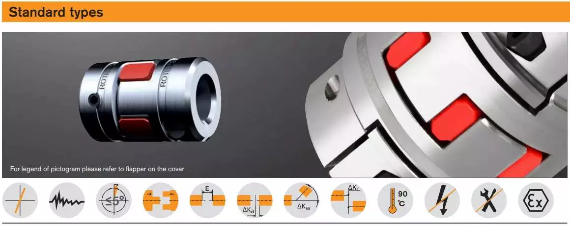
Modifications
The aim of this paper is to investigate the effects of coupling modifications. It shows that such modifications can adversely affect the performance of the coupling mechanism. Moreover, the modifications can be predicted using chemical physics methods. The results presented here are not exhaustive and further research is needed to understand the effects of such coupling modifications.
The modifications to coupling involve nonlinear structural modifications. Four examples of such modifications are presented. Each is illustrated with example applications. Then, the results are verified through experimental and simulated case studies. The proposed methods are applicable to large and complex structures. They are applicable to a variety of engineering systems, including nonlinear systems.
editor by czh 2022-12-30
China Stainless Steel Camlock Coupling Quick Couplings Type C Hose Couplings a coupling reaction
Merchandise Description
Material: Stainless Steel
Item Form: Camlock Coupling
Handle: Stainless Metal
Design :A B C D E F DC DP
Measurement: 1/2"-6"
Standard: A-A-59326(A)
|
US $0.1-1 / Piece | |
1 Piece (Min. Order) |
###
| Standard: | DIN, ANSI |
|---|---|
| Material: | Stainless Steel |
| Connection: | Quick Couplings |
| Surface Treatment: | Sand Blast |
| Head Type: | Round |
| Thread: | NPT/Bsp |
###
| Samples: |
US$ 1/Piece
1 Piece(Min.Order) |
|---|
###
| Customization: |
Available
|
|---|
|
US $0.1-1 / Piece | |
1 Piece (Min. Order) |
###
| Standard: | DIN, ANSI |
|---|---|
| Material: | Stainless Steel |
| Connection: | Quick Couplings |
| Surface Treatment: | Sand Blast |
| Head Type: | Round |
| Thread: | NPT/Bsp |
###
| Samples: |
US$ 1/Piece
1 Piece(Min.Order) |
|---|
###
| Customization: |
Available
|
|---|
Types of Couplings
A coupling is a device used to join two shafts together and transmit power. Its purpose is to join rotating equipment while permitting a degree of end movement and misalignment. There are many types of couplings, and it is important to choose the right one for your application. Here are a few examples of couplings.
Mechanical
The mechanical coupling is an important component in power transmission systems. These couplings come in various forms and can be used in different types of applications. They can be flexible or rigid and operate in compression or shear. In some cases, they are permanently attached to the shaft, while in other cases, they are removable for service.
The simplest type of mechanical coupling is the sleeve coupling. It consists of a cylindrical sleeve with an internal diameter equal to the diameter of the shafts. The sleeve is connected to the shafts by a key that restricts their relative motion and prevents slippage. A few sleeve couplings also have threaded holes to prevent axial movement. This type of coupling is typically used for medium to light-duty torque.
Another type of mechanical coupling is a jaw coupling. It is used in motion control and general low-power transmission applications. This type of coupling does not require lubrication and is capable of accommodating angular misalignment. Unlike other types of couplings, the jaw coupling uses two hubs with intermeshing jaws. The jaw coupling's spider is typically made of copper alloys. In addition, it is suitable for shock and vibration loads.
Mechanical couplings can be made from a variety of materials. One popular choice is rubber. The material can be natural or chloroprene. These materials are flexible and can tolerate slight misalignment.
Electrical
Electrical coupling is the process in which a single electrical signal is transferred from a nerve cell to another. It occurs when electrical signals from two nerve cells interact with each other in a way similar to haptic transmission. This type of coupling can occur on its own or in combination with electrotonic coupling in gap junctions.
Electrical coupling is often associated with oscillatory behavior of neurons. The mechanism of electrical coupling is complex and is studied mathematically to understand its effect on oscillatory neuron networks. For example, electrical coupling can increase or decrease the frequency of an oscillator, depending on the state of the neuron coupled to it.
The site of coupling is usually the junction of opposing cell membranes. The cellular resistance and the coupling resistance are measured in voltage-clamp experiments. This type of coupling has a specific resistance of 100 O-cm. As a result, the coupling resistance varies with the frequency.
The authors of this study noted that electrotonic coupling depends on the ratio between the resistance of the nonjunctional membranes and the junctional membranes. The voltage attenuation technique helps reveal the differences in resistance and shunting through the intercellular medium. However, it is unclear whether electrotonic coupling is electrostatically mediated.
Electrical coupling has also been suggested to play a role in the intercellular transfer of information. There are many examples that support this theory. A message can be a distinct qualitative or quantitative signal, which results in a gradient in the cells. Although gap junctions are absent at many embryonic interaction sites, increasing evidence suggests a role in information transfer.
Flexible
When it comes to choosing the right Flexible Coupling, there are several factors that you should take into account. Among these factors is the backlash that can be caused by the movement of the coupling. The reason for this problem is the fact that couplings that do not have anti-fungal properties can be easily infected by mold. The best way to avoid this is to pay attention to the moisture content of the area where you are installing the coupling. By following these guidelines, you can ensure the best possible installation.
To ensure that you are getting the most out of your flexible couplings, you must consider their characteristics and how easy they are to install, assemble, and maintain. You should also look for elements that are field-replaceable. Another important factor is the coupling's torsional rigidity. It should also be able to handle reactionary loads caused by misalignment.
Flexible couplings come in many different types. There are diaphragm and spiral couplings. These couplings allow for axial motion, angular misalignment, and parallel offset. They have one-piece construction and are made from stainless steel or aluminum. These couplings also offer high torsional stiffness, which is beneficial for applications requiring high torques.
Flexible couplings have several advantages over their rigid counterparts. They are designed to handle misalignments of up to seven degrees and 0.025 inches. These characteristics are important in motion control applications. Flexible couplings are also inexpensive, and they do not require maintenance.
Beam
A beam coupling is a type of mechanical coupling, usually one solid piece, that connects two mechanical parts. Its performance is largely determined by the material used. Typical materials include stainless steel, aluminum, Delrin, and titanium. The beam coupling is rated for different speeds and torques. The coupling should be selected according to the application. In addition to the material, the application should also consider the speed and torque of the system.
There are two main types of beam couplings. The first is the helical beam coupling, which has a continuous multi spiral cut. This type of coupling offers a high degree of flexibility and compensates for a high degree of misalignment. The second type of beam coupling is the helical shaft coupling, which has a low torsional stiffness, which makes it ideal for small torque applications.
Another type of beam coupling is the multiple beam design, which combines two beams. It allows for more tolerance in manufacturing and installation and protects expensive components from excessive bearing loads. It also helps keep beams shorter than a single beam coupling. This type of coupling also enables a higher torque capacity and torsional stiffness.
Beam couplings can be manufactured with different materials, including stainless steel and aluminum. The "A" series is available in aluminum and stainless steel and is ideal for general-purpose and light-duty applications. It is also economical and durable. This type of coupling can also be used with low torque pumps or encoder/resolver systems.
Pin & bush
The Pin & bush coupling is a versatile, general-purpose coupling with high tensile bolts and rubber bushes. It can tolerate a wide range of operating temperatures and is suitable for use in oil and water-resistance applications. Its unique design enables it to be used in either direction. In addition, it requires no lubrication.
The pin bush coupling is a fail-safe coupling with a long service life and is used for high-torque applications. It provides torsional flexibility and dampens shocks, making it a flexible coupling that protects equipment and reduces maintenance costs. Its hubs are forged from graded cast iron for strength and durability. Besides, the coupling's elastomer elements reduce vibration and impact loads. It also accommodates a misalignment of up to 0.5 degrees.
Pin & bush couplings are a popular choice for a variety of different applications. This coupling features a protective flange design that protects the coupling flange from wear and tear. The coupling nut is secured to one flange, while a rubber or leather bush sits between the other flange. Its unique design makes it ideal for use in applications where misalignment is a small factor. The rubber bushing also helps absorb vibration and shock.
Mesh tooth
Mesh tooth couplings are used to transfer torque between two shafts and reduce backlash. However, mesh tooth couplings have some limitations. One disadvantage is the break-away friction factor in the axial direction. This problem is caused by the high contact force between the tooth and gear mesh. This can cause unpredictable forces on the shafts.
In this paper, we present a FEM model for mesh tooth coupling. We first validate the mesh density. To do so, we compute the bolt stress as a uniaxial tensile during the tightening process. We used different mesh sizes and mesh density to validate our results.
The mesh stiffness of gear pairs is influenced by lead crown relief and misalignment. For example, if one tooth is positioned too far in the axis, the mesh stiffness will be decreased. A misaligned gear pair will lose torque capacity. A mesh tooth coupling can be lubricated with oil.
An ideal mesh tooth coupling has no gaps between the teeth, which reduces the risk of uneven wear. The coupling's quality exposed fasteners include SAE Grade 5 bolts. It also offers corrosion resistance. The couplings are compatible with industrial environments. They also eliminate the need for selective assembly in sleeve couplings.
editor by czh 2022-12-19
China manufacturer Stainless Steel Female Threading Sanitary Grade Nipple Couplings (JN-FL2001) near me factory
Error:获取返回内容失败,
Your session has expired. Please reauthenticate.
| JoNeng valves company was started in 2007. Located in the stainless steel industry zone, Wenzhou, China. |
| Totally 130nos of workers and the factory Covers 5000m2. Till now, we have 34 sets of LG Mazak machines and other local CNC machines; Plus, we have 2 sets of automatic machining unit. To assure better quality, we have the full inspecting quality control equipment: 1nos Ra roughness instrument, 3nos stainless steel spectrometer, numbers of roundness instrument, numbers of thickness instrument, numbers of radius instrument, 3 nos pressure testing center. |
| JoNeng valves provides the following sanitary flow control components: Stainless steel sanitary valve ( stainless steel sanitary butterfly valve, sanitary diaphragm valve, sanitary check valve, sanitary ball valve, sanitary CPM valve, ...) stainless steel sanitary pipe fittings( stainless steel sanitary elbow, tee, clamp, ferrule, union, cleaning ball, sight glass, filter...) Stainless steel Sanitary pump ( stainless steel sanitary centrifugal pump, rotary lobe pump, CIP pump) |
| JoNeng services for food, beverage, dairy, chemical, bioth, pharmaceutical, and etc industries. |
| JoNeng customers are from 55 different countries.After so many years, JoNeng know more about different requirements from different countries' customers. JoNeng valves believes in "What we say, what we do". We always believe honesty and responsibility is the only way leading to long term business relationship. Trying our best for customers and put ourselves into customers' shoes. Our commitment " Never let customers leave us because our poor quality". Making business with us, making friends with us. |
###
| Production Lines | Stainless steel sanitary pipe fittings' line, machining line, sanitary manhole line, | |
| Product Range | sanitary butterfly Valve, sanitary diaphragm valve, sanitary pipe fittings, union, ferrule, sight glass, manhole cover, safety valve, sampling valve.... | |
| Year Established | 2007 | |
| Factory Size in Square Meters | 5000M2 | |
| NO. OF TOTAL STAFF | 130 | |
| Production Capital | 8 000 000 USD | |
| Detail capacity | Manhole covers | 12000nos |
| Pipe fittings | 150000nos | |
| Ferrules, unions, connectors | 200000nos | |
| Diaphragm valves | 15000nos | |
| Butterfly valves | 20000nos | |
| Investment in Manufacturing Equipment | 750000usd | |
| Details of equipment | For machining parts 29 nos of LG Mazak CNC Machines 4 nos of local CNC machines 2 nos of automatic CNC center 12 nos of plain lathe For pipe fittings 4 nos of press 3 nos of cutting machine 3 nos of chamfering machine We also have the following quipments 4 nos of polishing machine 12 nos of grinding machine 3 nos of laser marking machine 3 nos of pressure testing machine 1 nos of temperature testing machine 3 nos of spectro instrument 1 nos of surface roughness device |
|
| Primary Competitive Advantages | Strict inspection , honest business way, fast revert on order problem | |
| Stocked materials | Big quantity for raw forging of butterfly valve, diaphragm valve, ferrule, union, adapters, pipe fittings, clamps, sight glass, safety valve, manhole cover, | |
| OEM Services Provided | yes | |
| Design Service Offered | yes | |
| Sales Volume | 6 000 000 usd | |
| Export Percentage | 80% | |
| MAIN MARKET | USA, Germany, Hungary, Canada, Thailand, Holland, England, South Africa,Indonesia, Saudi, India, New Zealand, Australia, Middle East... | |
| Own Brand Name | JoNeng | |
###
| HOW DO WE MAKE THE QUALITY CONTROL | |
| For Raw Materials |
1. Material control from raw materials. For raw material checking, we check 100% by chemical liquid. Any property mistakes would be rejected. 2. Sand hole inspection after raw materials are machining before polishing. 3. Carbon component report can be provided if needed 4. Mechanics test report can be provided if needed |
| For New products | 5. 2nos of new samples to be checked against technical drawing. Testing report is provided to customers before bulk production. |
| For finished materials | 6. For valves, pressure testing and temperature testing is required for each valve. 7. After we get the finished products, we check for surface roughness, thickness equality, roundness, size measurement and sand holes again. 8. For all finished products, the checking quantity is not less than 10% of total quantity. 9. Before shipment, we check for the quantity of each product in order to find out any missing quantity or wrong product. |
Worm Gear Motors
Worm gear motors are often preferred for quieter operation because of the smooth sliding motion of the worm shaft. Unlike gear motors with teeth, which may click as the worm turns, worm gear motors can be installed in a quiet area. In this article, we will talk about the CZPT whirling process and the various types of worms available. We'll also discuss the benefits of worm gear motors and worm wheel.
worm gear
In the case of a worm gear, the axial pitch of the ring pinion of the corresponding revolving worm is equal to the circular pitch of the mating revolving pinion of the worm gear. A worm with one start is known as a worm with a lead. This leads to a smaller worm wheel. Worms can work in tight spaces because of their small profile.
Generally, a worm gear has high efficiency, but there are a few disadvantages. Worm gears are not recommended for high-heat applications because of their high level of rubbing. A full-fluid lubricant film and the low wear level of the gear reduce friction and wear. Worm gears also have a lower wear rate than a standard gear. The worm shaft and worm gear is also more efficient than a standard gear.
The worm gear shaft is cradled within a self-aligning bearing block that is attached to the gearbox casing. The eccentric housing has radial bearings on both ends, enabling it to engage with the worm gear wheel. The drive is transferred to the worm gear shaft through bevel gears 13A, one fixed at the ends of the worm gear shaft and the other in the center of the cross-shaft.
worm wheel
In a worm gearbox, the pinion or worm gear is centered between a geared cylinder and a worm shaft. The worm gear shaft is supported at either end by a radial thrust bearing. A gearbox's cross-shaft is fixed to a suitable drive means and pivotally attached to the worm wheel. The input drive is transferred to the worm gear shaft 10 through bevel gears 13A, one of which is fixed to the end of the worm gear shaft and the other at the centre of the cross-shaft.
Worms and worm wheels are available in several materials. The worm wheel is made of bronze alloy, aluminum, or steel. Aluminum bronze worm wheels are a good choice for high-speed applications. Cast iron worm wheels are cheap and suitable for light loads. MC nylon worm wheels are highly wear-resistant and machinable. Aluminum bronze worm wheels are available and are good for applications with severe wear conditions.
When designing a worm wheel, it is vital to determine the correct lubricant for the worm shaft and a corresponding worm wheel. A suitable lubricant should have a kinematic viscosity of 300 mm2/s and be used for worm wheel sleeve bearings. The worm wheel and worm shaft should be properly lubricated to ensure their longevity.
Multi-start worms
A multi-start worm gear screw jack combines the benefits of multiple starts with linear output speeds. The multi-start worm shaft reduces the effects of single start worms and large ratio gears. Both types of worm gears have a reversible worm that can be reversed or stopped by hand, depending on the application. The worm gear's self-locking ability depends on the lead angle, pressure angle, and friction coefficient.
A single-start worm has a single thread running the length of its shaft. The worm advances one tooth per revolution. A multi-start worm has multiple threads in each of its threads. The gear reduction on a multi-start worm is equal to the number of teeth on the gear minus the number of starts on the worm shaft. In general, a multi-start worm has two or three threads.
Worm gears can be quieter than other types of gears because the worm shaft glides rather than clicking. This makes them an excellent choice for applications where noise is a concern. Worm gears can be made of softer material, making them more noise-tolerant. In addition, they can withstand shock loads. Compared to gears with toothed teeth, worm gears have a lower noise and vibration rate.
CZPT whirling process
The CZPT whirling process for worm shafts raises the bar for precision gear machining in small to medium production volumes. The CZPT whirling process reduces thread rolling, increases worm quality, and offers reduced cycle times. The CZPT LWN-90 whirling machine features a steel bed, programmable force tailstock, and five-axis interpolation for increased accuracy and quality.
Its 4,000-rpm, 5-kW whirling spindle produces worms and various types of screws. Its outer diameters are up to 2.5 inches, while its length is up to 20 inches. Its dry-cutting process uses a vortex tube to deliver chilled compressed air to the cutting point. Oil is also added to the mixture. The worm shafts produced are free of undercuts, reducing the amount of machining required.
Induction hardening is a process that takes advantage of the whirling process. The induction hardening process utilizes alternating current (AC) to cause eddy currents in metallic objects. The higher the frequency, the higher the surface temperature. The electrical frequency is monitored through sensors to prevent overheating. Induction heating is programmable so that only certain parts of the worm shaft will harden.
Common tangent at an arbitrary point on both surfaces of the worm wheel
A worm gear consists of two helical segments with a helix angle equal to 90 degrees. This shape allows the worm to rotate with more than one tooth per rotation. A worm's helix angle is usually close to 90 degrees and the body length is fairly long in the axial direction. A worm gear with a lead angle g has similar properties as a screw gear with a helix angle of 90 degrees.
The axial cross section of a worm gear is not conventionally trapezoidal. Instead, the linear part of the oblique side is replaced by cycloid curves. These curves have a common tangent near the pitch line. The worm wheel is then formed by gear cutting, resulting in a gear with two meshing surfaces. This worm gear can rotate at high speeds and still operate quietly.
A worm wheel with a cycloid pitch is a more efficient worm gear. It reduces friction between the worm and the gear, resulting in greater durability, improved operating efficiency, and reduced noise. This pitch line also helps the worm wheel engage more evenly and smoothly. Moreover, it prevents interference with their appearance. It also makes worm wheel and gear engagement smoother.
Calculation of worm shaft deflection
There are several methods for calculating worm shaft deflection, and each method has its own set of disadvantages. These commonly used methods provide good approximations but are inadequate for determining the actual worm shaft deflection. For example, these methods do not account for the geometric modifications to the worm, such as its helical winding of teeth. Furthermore, they overestimate the stiffening effect of the gearing. Hence, efficient thin worm shaft designs require other approaches.
Fortunately, several methods exist to determine the maximum worm shaft deflection. These methods use the finite element method, and include boundary conditions and parameter calculations. Here, we look at a couple of methods. The first method, DIN 3996, calculates the maximum worm shaft deflection based on the test results, while the second one, AGMA 6022, uses the root diameter of the worm as the equivalent bending diameter.
The second method focuses on the basic parameters of worm gearing. We'll take a closer look at each. We'll examine worm gearing teeth and the geometric factors that influence them. Commonly, the range of worm gearing teeth is one to four, but it can be as large as twelve. Choosing the teeth should depend on optimization requirements, including efficiency and weight. For example, if a worm gearing needs to be smaller than the previous model, then a small number of teeth will suffice.

